Buying welding automation across borders is not simply a robot-selection exercise. It is a process-control decision involving equipment, people, materials, software, and local support. Dr. John C. Lippold, a respected welding researcher and educator, has emphasized a practical principle: “Sound welds depend on controlling the process, not merely examining the result.” That principle matters when a supplier promises high speed but cannot explain arc stability, fixture accuracy, or inspection procedures.
Global buyers should examine the complete production environment. Check the robot’s payload, torch access, duty cycle, wire compatibility, and programming method. Ask how the system handles uneven parts, changing joint gaps, and different material thicknesses. A cell that performs perfectly on a sample frame may struggle beside a factory door, where dust, voltage fluctuations, and limited floor space exist.
Local service matters greatly. Spare contact tips, trained technicians, software updates, and emergency response can protect production continuity. Confirm applicable certifications and electrical requirements before shipment. Review operator training, documentation, warranty terms, and integration responsibilities in writing. Do not accept vague promises.
The lowest quotation may look attractive. It may also hide tooling costs, installation delays, or difficult maintenance. That assumption often fails. Buyers should request a realistic weld trial using their materials and joint designs. Measure cycle time, defect rates, changeover effort, and operator involvement. Welding automation should reduce risk, not merely add motion. Some plans will need revision after testing. That is not failure. It is responsible engineering.
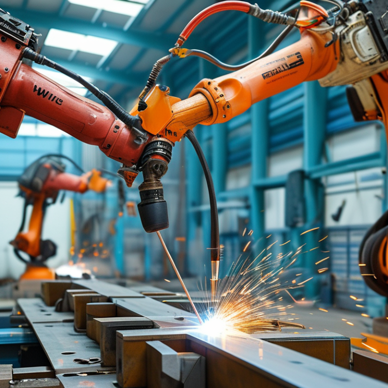
Define welding automation goals before comparing equipment, cells, or control systems. Start with measurable requirements: parts per shift, takt time, arc-on time, weld size, defect limits, and operator involvement. Record material grades, joint geometry, tolerances, fixture access, and expected product changes. A cell designed for one stable part may struggle with five similar-looking assemblies.
Use real production data, not optimistic estimates. The International Federation of Robotics reported 541,302 industrial robots were installed worldwide in 2023, showing strong automation adoption. However, installation volume does not guarantee productivity. A useful target should connect cycle time with first-pass yield, rework hours, and traceability. The Deloitte and Manufacturing Institute 2024 study projects 3.8 million manufacturing job openings in the United States by 2033, with about 1.9 million potentially unfilled. Labor pressure matters, but automation should not replace process discipline.
Define the business case clearly. Include fixture changes, programming time, maintenance skills, spare parts, training, and energy use. Measure the current process for at least several shifts. Small flaws become expensive later. One imperfect weld sample can reveal poor fit-up, unstable wire feeding, or incorrect shielding gas flow. Leave room for manual intervention when part variation is unavoidable. A fully automated plan may look efficient on paper, yet fail beside a real welding table. Sources: International Federation of Robotics, World Robotics 2024; Deloitte and The Manufacturing Institute, Creating a Resilient Manufacturing Workforce, 2024.
Before selecting an automated welding system, define measurable production targets. The planning benchmarks below show common goals for a high-volume welding cell, including higher output, shorter cycle times, improved uptime, fewer defects, and faster changeovers.
10 Welding Automation Tips for Global Buyers
Automated welding succeeds when the workpiece, joint, and process match. I have seen strong equipment fail because material preparation was inconsistent. Identify the exact grade, thickness, coating, and heat sensitivity before comparing systems. Mild steel, stainless steel, and aluminum each respond differently to heat input and shielding conditions. Record surface oil, scale, and moisture risks. Small details matter.
Tips: 1. Confirm material certificates. 2. Measure thickness variation. 3. Check thermal distortion. 4. Select joint access carefully. 5. Control root gaps. 6. Match wire chemistry. 7. Compare MIG, TIG, laser, and resistance welding. 8. Test shielding gas stability. 9. Add sensors for fit-up changes. 10. Validate weld inspection methods. Keep testing practical. A short production trial often reveals more than a polished demonstration.
Joint design should support torch reach, consistent travel, and safe fixturing. Narrow gaps may reduce filler use, but they demand better tolerance control. Deep corners can create incomplete fusion or difficult inspection angles. Process selection also depends on volume, cycle time, appearance, and repair access. Ask for cross-sections, destructive tests, and repeatability data. Do not trust one perfect sample. Real parts vary. Even experienced teams sometimes underestimate cleaning time, fixture maintenance, or operator training. Build those costs into the purchase decision, then review them after the first production month.
| No. | Automation Tip | Key Evaluation Dimension | Practical Data or Benchmark | Suitable Welding Approach | Main Risk and Recommended Control |
|---|---|---|---|---|---|
| 1 | Verify the base material before selecting equipment. | Material type, thickness, thermal conductivity, surface condition, and weldability. | Carbon steel, stainless steel, and aluminum require different heat input, shielding, consumables, and torch configurations. Aluminum transfers heat rapidly and forms an oxide layer that must be managed. | GMAW, GTAW, or laser welding selected according to material and thickness; use qualified procedures and material certificates. | Incorrect material assumptions can cause porosity, cracking, or lack of fusion. Confirm grade, thickness range, coating, and cleanliness during sample testing. |
| 2 | Match the joint design to the automation capability. | Joint type, access, fit-up tolerance, root gap, and weld-position requirements. | Fillet joints are generally easier to automate than deep groove joints. Larger root gaps and inconsistent alignment increase the need for seam tracking and adaptive control. | Use robotic GMAW for repeatable fillets and butt joints; add laser or touch sensing when joint location varies. | Poor fit-up may create burn-through or incomplete fusion. Establish drawing tolerances, fixture checks, and a first-article approval process. |
| 3 | Choose the process based on thickness and production volume. | Material thickness, deposition rate, cycle time, duty cycle, and required weld quality. | GMAW is widely used for automated carbon-steel fabrication. GTAW provides precise control but is slower. Laser welding can reduce heat input and distortion when joint preparation is highly consistent. | Compare GMAW, pulsed GMAW, GTAW, FCAW, submerged arc welding, and laser welding through a timed production trial. | A process that is technically suitable may still be uneconomical. Compare total cycle time, consumables, maintenance, programming, and rework cost. |
| 4 | Define realistic dimensional tolerances. | Part variation, fixture repeatability, distortion allowance, and inspection method. | Automation performs best when the part and fixture present a repeatable joint. Tolerance requirements should be specified on drawings rather than left to operator judgment. | Use precision fixtures, locating pins, clamping verification, and offline measurement where part variation is significant. | Excessive fixture variation leads to frequent touch-ups and downtime. Validate fixture repeatability across multiple production cycles. |
| 5 | Evaluate weld position and accessibility. | Flat, horizontal, vertical, or overhead position; torch angle; cable routing; and collision clearance. | Flat and horizontal welding generally offer better control of the molten pool than vertical or overhead welding. Complex access may require positioners or multi-axis robotic motion. | Combine a robot with a positioner, rotating table, or coordinated external axis when possible. | Restricted access can cause collisions and inconsistent bead profiles. Perform reach, payload, and interference studies before purchase. |
| 6 | Specify sensing and adaptive control according to variation. | Joint-location variation, gap changes, surface reflectivity, and required correction speed. | Touch sensing can locate a joint before welding. Through-arc sensing can correct certain joint deviations during GMAW. Laser vision can support non-contact seam measurement. | Select touch, through-arc, or laser sensing after testing the actual workpiece, coating, geometry, and lighting conditions. | Sensors can fail because of spatter, reflections, smoke, or poor calibration. Include cleaning schedules, calibration checks, and fault recovery logic. |
| 7 | Control heat input and distortion. | Current, voltage, travel speed, sequence, interpass temperature, and material thickness. | Heat input is commonly estimated from voltage, current, and travel speed; higher heat input generally increases the risk of distortion and a larger heat-affected zone. | Use pulsed GMAW, controlled travel speed, balanced weld sequences, copper backing, or laser welding where appropriate. | Excessive heat may cause warping or metallurgical damage. Confirm procedure limits and inspect distortion after cooling, not only during welding. |
| 8 | Plan shielding gas and consumable management. | Gas composition, flow stability, wire or filler compatibility, storage, and supply availability. | Shielding-gas selection depends on material and process. Excessive flow can create turbulence and draw in air, while insufficient flow can cause porosity. | Use regulated gas delivery, flow monitoring, dry consumable storage, and automatic wire-feed or filler replenishment when justified. | Moisture, leaks, blocked nozzles, and incorrect wire diameter can reduce weld quality. Add preventive checks and lot traceability. |
| 9 | Build inspection and traceability into the system. | Acceptance criteria, inspection frequency, data collection, and applicable welding standards. | Visual inspection is commonly supplemented by non-destructive testing such as liquid penetrant, magnetic particle, ultrasonic, or radiographic testing according to the application. | Connect the welding controller with barcode, RFID, or production records to associate workpieces with programs, parameters, and inspection results. | Unverified welds create quality and compliance exposure. Define acceptance criteria, calibration intervals, and record-retention requirements before commissioning. |
| 10 | Compare total ownership cost, not only equipment price. | Labor, consumables, energy, maintenance, programming, training, spare parts, uptime, and payback period. | A realistic evaluation should include utilization, changeover time, rework, consumable waste, planned maintenance, and the cost of downtime over the expected service life. | Request a production-cell simulation, sample welds, cycle-time report, maintenance plan, training scope, and spare-parts list. | A low initial price may hide integration and service costs. Use a standardized total-cost-of-ownership model and verify assumptions with a site acceptance test. |
Compare automation systems by production volume, weld type, and operator skill. A robotic cell suits repeatable joints, while a compact automated carriage may fit varied workpieces. Check torch movement, welding position, cycle time, and adjustment range. Ask for real test results, not only catalog figures. I once approved a system after watching a perfect sample weld. The production floor exposed poor access around narrow corners.
Equipment features need practical comparison. Review wire diameter range, power stability, cooling capacity, sensor accuracy, and maintenance access. A simple interface helps new operators work safely. Remote monitoring can reduce downtime, but only with reliable network support. Keep spare contact tips, cables, and sensors available. Small failures become expensive delays. Check noise, heat, ventilation, and floor space before installation.
Compatibility often decides the purchase. Confirm voltage, frequency, gas supply, wire materials, fixture dimensions, and communication protocols. The system should connect with existing welding machines and production software. Request interface drawings and sample data files. Test unfamiliar materials under actual factory conditions. Compatibility claims may hide extra adapters or custom programming. I would also inspect training documents and service response times. They are easy to overlook, yet they shape daily performance. Leave room for future tooling changes, because today’s efficient layout may restrict tomorrow’s product.
A low quote means little without traceable quality evidence. Request weld procedure specifications, qualification records, calibration certificates, and recent inspection results. ISO 9001 certification helps, but it does not prove every weld is consistent. Ask for sample welds using your material, thickness, joint design, and cycle time. Inspect bead profile, penetration, spatter, and distortion. Do not trust brochures alone.
The International Federation of Robotics reported 541,302 industrial robots installed worldwide in 2023. This growth increases supplier competition, but also makes technical screening more important. Confirm compliance with applicable safety requirements, including ISO 10218, ISO 12100, and local electrical rules. Check guarding, interlocks, emergency stops, fume extraction, and operator training. In the United States, OSHA limits airborne hexavalent chromium exposure to 5 micrograms per cubic meter over eight hours. Your destination may require different controls.
Technical support should be measurable. Ask for response times, spare-parts availability, remote diagnostics, software updates, and local service coverage. Require installation training and documented acceptance testing. A supplier should explain how it handles wire-feed errors, torch collisions, porosity, and power interruptions. I have seen projects fail because “support included” meant email support across several time zones. The checklist can still miss reality. Test communication before payment, and include service duties in the contract.
10 Welding Automation Tips for Global Buyers
Calculate Total Ownership Costs, Implementation Needs, and Scalability
A factory-floor trial taught us that purchase price rarely reflects the real investment. Global buyers should calculate equipment, tooling, software, shipping, installation, training, maintenance, energy, and replacement parts. Small errors compound. Request a five-year ownership model with labor savings and expected uptime. Use local currency scenarios when exchange rates may affect budgets.
Implementation needs deserve equal attention. Check floor space, power capacity, ventilation, safety guarding, network access, and operator skills before signing. Confirm who will integrate fixtures, sensors, welding controls, and production data. A detailed acceptance test should measure cycle time, weld consistency, changeover time, and fault recovery. Do not rely only on a polished demonstration. Production metal behaves differently.
Scalability should be practical, not promotional. Ask whether the system can handle new part sizes, additional stations, different welding procedures, and higher volumes. Modular tooling and open data interfaces can reduce future disruption. Plan spare capacity, but avoid buying unused automation too early. We once underestimated training time by several weeks. That mistake delayed output and increased overtime. A phased rollout, with documented lessons from the pilot cell, often provides better control than a sudden factory-wide launch. Local service coverage and technician response times also belong in the cost model. Workers should help test the workflow; their feedback may expose problems engineers miss.